Simulate saturated single phase flow in fractured porous media: tests for inclined elements
There are four tests for the finite element analyses with inclined elements, which are the benchmarks to simulate the saturated single phase flow in fractured porous media. The correctness of the implementation of the inclined element approach is verified by the obtained flow, or flow velocity, orientation of these four benchmarks.
Flow in an inclined plane
Under this topic, there are two benchmarks using the same 2D mesh on an inclined
plane. The input files are given in the sub-directory of Inclined2DMesh,
which includes one for hydro-steady state flow and another for transient flow
under the fixed pressure difference on the top and the bottom boundary and
the gravitational force.
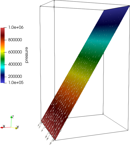
For the hydro-steady state one, it gives zero velocity. For the transient
simulation, the orientation calculated velocity is shown in the following
figure, which is parallel to the mesh plane as what expected.
Flow in rock matrix with two intersected fractures
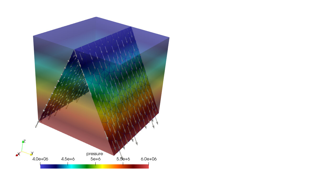
The input files are given in the sub-directory of FractureIn3D. This benchmark tests the case of the mesh contains both 3D elements and inclined 2D element. The analysed domain has two intersected fractures. The brick shape domain is discretised into tetrahedra, while the two planes are discretised into triangles. The permeability of the continuous domain is
$$k_{xx}=1.0\cdot 10^{-18}, k_{yy}=3.0\cdot 10^{-18}, k_{xx}=3.0\cdot 10^{-18}\, \text{m}^2,$$and the permeability of fractures are
$$ 10^{-14}\, \text{m}^2, \quad \text{and } 10^{-15}\, \text{m}^2,$$
respectively. The flow is
driven by the fixed pressure difference on the top and the bottom boundaries
and the gravity. The following figure shows the pressure distribution and
the flow orientation on the fractures. It can be seen that the flow orientation
is exactly parallel to the fracture planes as what expected.
Line elements on a sphere
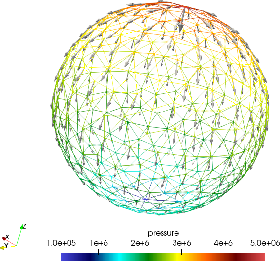
The input files are given in the sub-directory of 1Din3D.
This an artificial example is used to test the simulation with a mesh only with
inclined line elements. A sphere surface is used to discretise into triangle
elements, and then all the edges of the elements are used as line elements of
the mesh for this benchmark. That means all lines elements are on a sphere.
A fixed pressure difference is applied at the two poles of the sphere. As shown
in the following figure, the computed flow orientation is exactly on
the tangent of the boundary of the vertical splices of the sphere.
This article was written by Wenqing Wang. If you are missing something or you find an error please let us know.
Generated with Hugo 0.147.9
in CI job 683680
|
Last revision: December 20, 2025
Commit: chore: fix spelling mistakes fbc5f730
| Edit this page on