IntegrateBoreholesIntoMesh
Description
This tool is used to integrate line elements representing boreholes into a pre-existing 3D mesh. Corresponding nodes matching the (x,y)-coordinates given in the gml-file are found in the mesh and connected from top to bottom via line elements. Each borehole (i.e. all points at a given (x,y)-location but at different depths) is assigned a unique material ID. Vertical limits of boreholes can be specified via Material IDs and/or elevation. Points that do not match any mesh nodes or are located outside the mesh are ignored.
Usage
    IntegrateBoreholesIntoMesh  -i <input file name> -o <output file name>
                                 -g <geometry file name> [--min-id <a number>]
                                 [--max-id <a number>] [--min-elevation <a number>]
                                 [--max-elevation <a number>] [--] [--version] [-h]

Where:
   -i <input file name>,  --input <input file name>
     (required)  Name of the input mesh (*.vtu)

   -o <output file name>,  --output <output file name>
     (required)  Name of the output mesh (*.vtu)

   -g <geometry file name>,  --geo <geometry file name>
     (required)  Name of the geometry file (*.gml)

   --min-id <a number>
     Minimum MaterialID for an integrated borehole

   --max-id <a number>
     Maximum MaterialID for an integrated borehole

   --min-elevation <a number>
     Minimum elevation for an integrated borehole

   --max-elevation <a number>
     Maximum elevation for an integrated borehole

   --,  --ignore_rest
     Ignores the rest of the labeled arguments following this flag.

   --version
     Displays version information and exits.

   -h,  --help
Displays usage information and exits.Example
In this example we apply the tool to integrate boreholes into a mesh. For this purpose we need to generate a .gml-file that holds the information about the x-y-coordinates for these boreholes. The .gml-file is given as:
<?xml version="1.0" encoding="ISO-8859-1"?>
<!DOCTYPE OGS-GML-DOM>
<OpenGeoSysGLI xmlns:xsi="http://www.w3.org/2001/XMLSchema-instance" xmlns:ogs="http://www.opengeosys.org">
 <name>Sondeneigenschaften</name>
 <points>
  <point y="5823820.41142969" id="1" z="0.000000000000000" x="394740.68790251"/>
  <point y="5823853.29162632" id="2" z="0.000000000000000" x="394642.047312616"/>
 </points>
</OpenGeoSysGLI>It is mandatory that the x-y-coordinates of the boreholes are aligned with nodes of the input mesh. Also they must be given with same precision as the mesh nodes, otherwise the tool will not find the nodes.
IntegrateBoreholesIntoMesh -i input_3Dmesh.vtu -o boreholes_3Dmesh.vtu -g boreholes_xy.gml --min-id 2 --max-id 4NOTE: If some boreholes are given at the beginning of the meshing process, it is recommended to use the OpenGeoSys DataExplorer – Manual / Download. At first, the nodes for boreholes can be integrated into the mesh, when the mesh is generated from a geometry. For this purpose, the boreholes and the boundaries of the geometry need to be imported in DataExplorer. Then this mesh can be used to create a 3D mesh, either with the DataExplorer or with createLayeredMeshfromRaster, which then can be used for integrating boreholes. This procedure is useful because the mesh is generated in a way that the coordinates of the boreholes are nodes in the mesh. Otherwise the borehole’s coordinates need to be adjusted according to a existing mesh. This process is schematically depicted in Fig.1, below.
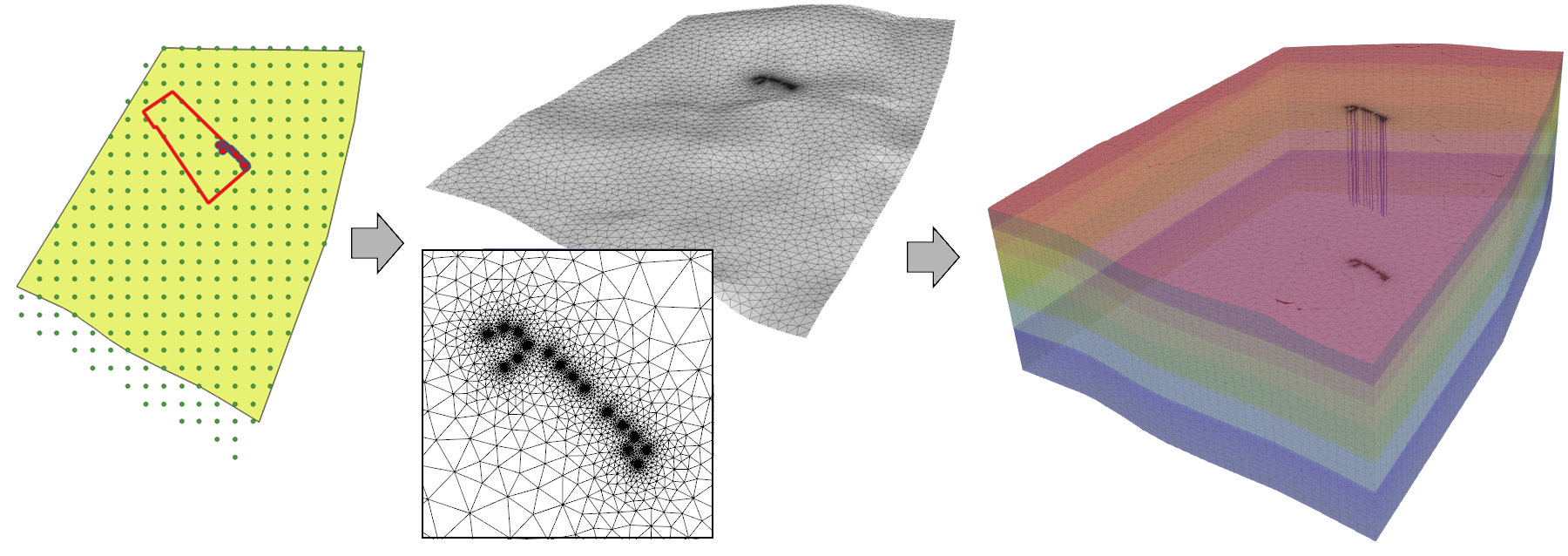
Fig.1 A schematic to visualize the methods of the tool. It does not refer to the upper example.
This article was written by Julian Heinze. If you are missing something or you find an error please let us know.
Generated with Hugo 0.147.9
in CI job 577984
|
Last revision: May 22, 2025
Commit: Remove deprecated TES process 6477209a
| Edit this page on