Pre-notched shear test
![]() This page is based on a Jupyter notebook.
This page is based on a Jupyter notebook.


Problem description
In order to verify the anisotropic phase field model detailed in (Ziaei-Rad et al., 2022), we present a single edge notched shear test specifically designed for materials with anisotropic/orthotropic behavior in the phase field approach to fracture to account for the tension–compression asymmetry. We generalize two existing models for tension-compression asymmetry in isotropic materials, namely the volumetric-deviatoric (Amor et al., 2009) and no-tension model (Freddi and Royer-Carfagni, 2010), towards materials with anisotropic nature.
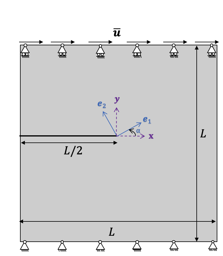
The geometry and boundary conditions for this example is shown in the following Figure.
We consider a square plate with an initial horizontal crack placed at the middle height from the left outer surface to the center of the specimen. Plane strain condition was assumed for sake of less computational costs. The user is free to choose either $\texttt{AT}_1$ or $\texttt{AT}_2$ as for the phase field model.
The boundary conditions are as follows. The displacement along any direction on the bottom edge ($y=-L/2$) was fixed to zero. Also, the displacement at the top edge ($y = L/2$) was prescribed along the $x$-direction, where the $y$-direction was taken to be zero.
Two helper functions
import os…
(click to toggle)
import os
import shutil
import time
from pathlib import Path
from subprocess import run
from types import MethodType
from xml.dom import minidom

import matplotlib.pyplot as plt
import numpy as np
import ogstools as ot
import pyvista as pv
out_dir = Path(os.environ.get("OGS_TESTRUNNER_OUT_DIR", "_out"))…
(click to toggle)
out_dir = Path(os.environ.get("OGS_TESTRUNNER_OUT_DIR", "_out"))
if not out_dir.exists():
    out_dir.mkdir(parents=True)

output_dir = out_dir

# define a method to replace a specific curve (analogue to replace_parameter method)


def replace_curve(
    self,
    name=None,
    value=None,
    coords=None,
    parametertype=None,
    valuetag="values",
    coordstag="coords",
):
    root = self._get_root()
    parameterpath = "./curves/curve"
    parameterpointer = self._get_parameter_pointer(root, name, parameterpath)
    self._set_type_value(parameterpointer, value, parametertype, valuetag=valuetag)
    self._set_type_value(parameterpointer, coords, parametertype, valuetag=coordstag)


# define a method to change timstepping in project file


def set_timestepping(model, repeat_list, delta_t_list):
    model.remove_element(
        xpath="./time_loop/processes/process/time_stepping/timesteps/pair"
    )
    for i in range(len(repeat_list)):
        model.add_block(
            blocktag="pair",
            parent_xpath="./time_loop/processes/process/time_stepping/timesteps",
            taglist=["repeat", "delta_t"],
            textlist=[repeat_list[i], delta_t_list[i]],
)Run ogs with specified parameters
def ogs_ortho(…
(click to toggle)
def ogs_ortho(
    phasefield_model,
    energy_split_model,
    length_scale=1.0,
    bc_displacement=1.0,
    ts_coords="0 1.0",
    values="0 1.0",
    repeat_list=None,
    delta_t_list=None,
    hypre=True,
    MPI=True,
    ncores=4,
):
    without_hypre = "-ksp_type cg -pc_type bjacobi -ksp_atol 1e-14 -ksp_rtol 1e-14"
    with_hypre = "-ksp_type cg -pc_type hypre -pc_hypre_type boomeramg -pc_hypre_boomeramg_strong_threshold 0.7 -ksp_atol 1e-8 -ksp_rtol 1e-8"

    prj_name = "shear.prj"
    print(
        f"> Running single edge notched shear test {phasefield_model} - {energy_split_model} ... <"
    )
    # fmt: off
    logfile = f"{out_dir}/log_{phasefield_model}_{energy_split_model}_out.txt"
    # fmt: on
    model = ot.Project(
        input_file=prj_name, output_file=f"{out_dir}/{prj_name}", MKL=True
    )

    # generate prefix from properties
    prefix = f"{phasefield_model}" + f"_{energy_split_model}"

    if MPI:
        # partition mesh
        run(
            f"NodeReordering -i shear.vtu -o {out_dir}/shear.vtu >> {logfile}",
            shell=True,
            check=True,
        )
        run(
            f"constructMeshesFromGeometry -m {out_dir}/shear.vtu -g shear.gml >> {logfile}",
            shell=True,
            check=True,
        )
        shutil.move("shear_top.vtu", f"{out_dir}/shear_top.vtu")
        shutil.move("shear_bottom.vtu", f"{out_dir}/shear_bottom.vtu")
        shutil.move("shear_left.vtu", f"{out_dir}/shear_left.vtu")
        shutil.move("shear_right.vtu", f"{out_dir}/shear_right.vtu")

        shutil.move("shear_p_0.vtu", f"{out_dir}/shear_p_0.vtu")
        shutil.move("shear_p_1.vtu", f"{out_dir}/shear_p_1.vtu")
        shutil.move("shear_p_2.vtu", f"{out_dir}/shear_p_2.vtu")
        shutil.move("shear_p_3.vtu", f"{out_dir}/shear_p_3.vtu")

        run(
            f"partmesh -s -o {out_dir} -i {out_dir}/shear.vtu >> {logfile}",
            shell=True,
            check=True,
        )
        run(
            f"partmesh -m -n {ncores} -o {out_dir} -i {out_dir}/shear.vtu -- {out_dir}/shear_top.vtu {out_dir}/shear_bottom.vtu {out_dir}/shear_left.vtu {out_dir}/shear_right.vtu >> {logfile}",
            shell=True,
            check=True,
        )
    else:
        run(
            f"NodeReordering -i shear.vtu -o {out_dir}/shear.vtu >> {logfile}",
            shell=True,
            check=True,
        )

    # change some properties in prj file
    model = ot.Project(
        input_file=prj_name, output_file=f"{out_dir}/{prj_name}", MKL=True
    )
    model.replace_parameter_value(name="ls", value=length_scale)
    model.replace_text(phasefield_model, xpath="./processes/process/phasefield_model")
    model.replace_text(
        energy_split_model, xpath="./processes/process/energy_split_model"
    )
    model.replace_text(prefix, xpath="./time_loop/output/prefix")

    model.replace_parameter_value(name="dirichlet_top", value=bc_displacement)
    model.replace_curve = MethodType(replace_curve, model)
    model.replace_curve(name="dirichlet_time", value=values, coords=ts_coords)

    if repeat_list is not None and delta_t_list is not None:
        set_timestepping(model, repeat_list, delta_t_list)
    else:
        set_timestepping(model, ["1"], ["1e-2"])
    if hypre is True:
        model.replace_text(
            with_hypre,
            xpath="./linear_solvers/linear_solver/petsc/parameters",
            occurrence=1,
        )
    else:
        model.replace_text(
            without_hypre,
            xpath="./linear_solvers/linear_solver/petsc/parameters",
            occurrence=1,
        )
    model.replace_text(Path("./shear.gml").resolve(), xpath="./geometry")
    model.write_input()
    # run ogs
    t0 = time.time()
    if MPI:
        print(f"  > OGS started execution with MPI - {ncores} cores...")
        run(
            f"mpirun --bind-to none -np {ncores} ogs {out_dir}/{prj_name} -o {output_dir} >> {logfile}",
            shell=True,
            check=True,
        )
    else:
        print("  > OGS started execution - ")
        run(
            f"ogs {out_dir}/{prj_name} -o {output_dir} >> {logfile}",
            shell=True,
            check=True,
        )
    tf = time.time()
print(" > OGS terminated execution. Elapsed time: ", round(tf - t0, 2), " s.")Input data
We used the parameters of Opalinus Clay listed in the following Table. Note that the critical surface energy $G_c$ was taken to be independent of the material orientation.
| Name | Value | Unit | Symbol |
|---|---|---|---|
| Young’s modulus | 6000 | MPa | $E_1$ |
| Young’s modulus | 13800 | MPa | $E_2$ |
| Young’s modulus | 13800 | MPa | $E_3$ |
| Poisson’s ratio | 0.22 | $-$ | $v_{12}$ |
| Poisson’s ratio | 0.44 | $-$ | $v_{23}$ |
| Poisson’s ratio | 0.22 | $-$ | $v_{13}$ |
| Shear modulus | 3200 | MPa | $G_{12}$ |
| Shear modulus | 1600 | MPa | $G_{23}$ |
| Shear modulus | 3200 | MPa | $G_{13}$ |
| Critical energy release rate | 0.5 | N/m | $G_{c}$ |
| Regularization parameter | 0.1 | mm | $\ell$ |
Run Simulations
In the following, we used a coarse mesh and also coarse time stepping only for sake of less computational costs. The user is free to apply finer mesh and time stepping.
# Alternative parameters…
(click to toggle)
# Alternative parameters
# phasefield_model = ['AT1', 'AT2']
# energy_split_model = ['OrthoVolDev', 'OrthoMasonry']

disp = 1.0e-6  # to change the intensity of the shear loading applied on the top edge
ls = 1.0e-4  # regularization parameter to capture the convergence, though some references consider it as a material parameter (ls/h=4, h=2.5e-5)

mpi_cores = 4  # MPI cores
## Here we only run one selected case. Based on the user's local device, more/less cores can be added to speed up/save resources.

# With the AT2 model, we are verifying two different anisotropic models, namely, orthotropic volumetric-deviatoric and orthotropic no-tension:
# For more details of each model, please see the reference of Ziaei Rad et al., 2022.
for b in ["OrthoMasonry", "OrthoVolDev"]:
    ogs_ortho(
        "AT2",
        b,
        length_scale=ls,
        bc_displacement=disp,
        repeat_list=["1"],
        delta_t_list=["1.e-2"],
        ncores=mpi_cores,
)> Running single edge notched shear test AT2 - OrthoMasonry ... <
> OGS started execution with MPI - 4 cores...
  > OGS terminated execution. Elapsed time:  110.72  s.
> Running single edge notched shear test AT2 - OrthoVolDev ... <
> OGS started execution with MPI - 4 cores...
> OGS terminated execution. Elapsed time: 66.29 s.
Results
In the following, the crack paths are shown for orthotropic volumetric–deviatoric and {no-tension} models under the shear loading with material orientation angle ($\alpha=0$). The user is free to change $\alpha$ to her desired angle in the prj file.
An implementation of the presented anisotropic phase-field formulation combined with the unsaturated HM approach is also underway.
Animation of crack propagation
The following film shows the crack propagation under the shear loading for no-tension model.
reader = pv.get_reader(f"{out_dir}/AT2_OrthoMasonry.pvd")…
(click to toggle)
reader = pv.get_reader(f"{out_dir}/AT2_OrthoMasonry.pvd")

plotter = pv.Plotter()

plotter.open_gif(f"{out_dir}/AT2_OrthoMasonry.gif")
pv.set_plot_theme("document")
for time_value in reader.time_values:
    reader.set_active_time_value(time_value)
    mesh = reader.read()[0]  # This dataset only has 1 block

    sargs = {
        "title": "Phase field",
        "title_font_size": 20,
        "label_font_size": 15,
        "n_labels": 5,
        "position_x": 0.3,
        "position_y": 0.2,
        "fmt": "%.1f",
        "width": 0.5,
    }
    clim = [0, 1.0]
    points = mesh.point_data["phasefield"].shape[0]
    xs = mesh.points[:, 0]
    ys = mesh.points[:, 1]
    pf = mesh.point_data["phasefield"]
    plotter.clear()
    plotter.add_mesh(
        mesh,
        scalars=pf,
        show_scalar_bar=False,
        clim=clim,  # colormap="coolwarm"
        scalar_bar_args=sargs,
        lighting=False,
    )
    plotter.add_text(f"Time: {time_value:.0f}", color="black")

    plotter.view_xy()
    plotter.write_frame()

plotter.close()[0m[33m2025-06-16 15:29:38.533 ( 194.482s) [ 755AEFCE1740]vtkXOpenGLRenderWindow.:1416 WARN| bad X server connection. DISPLAY=[0m
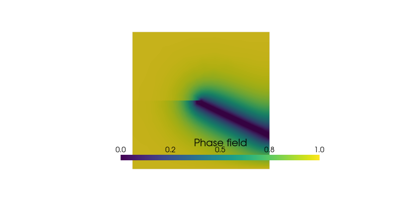
Phase field contours at the last time step
Also, below shows the phase field contours at the last time step for the orthotropic no-tension model.
reader = pv.get_reader(f"{out_dir}/AT2_OrthoMasonry.pvd")…
(click to toggle)
reader = pv.get_reader(f"{out_dir}/AT2_OrthoMasonry.pvd")

mesh = reader.read()[0]
pv.set_jupyter_backend("static")
p = pv.Plotter(shape=(1, 1), border=False)
p.add_mesh(
    mesh,
    scalars=pf,
    show_edges=False,
    show_scalar_bar=True,
    clim=clim,
    scalar_bar_args=sargs,
)

p.view_xy()
p.camera.zoom(1.0)
p.window_size = [800, 400]
p.show()
Post-processing
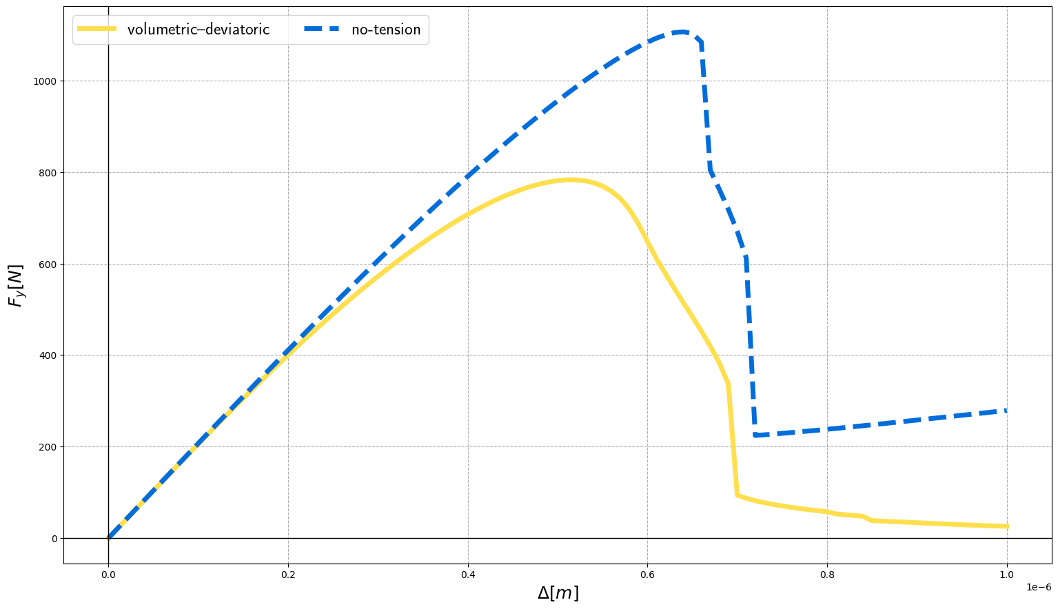
Figures compares the load-deflection curve for both models. As soon as the crack starts to propagate, the load drops.
# define function to obtain displacement applied on the top end of the square plate…
(click to toggle)
# define function to obtain displacement applied on the top end of the square plate
def displ_midpoint(filename):
    data = pv.read(filename)
    max_y = max(data.points[:, 1])
    return np.mean(
        data.point_data["displacement"][:, 0],
        where=np.transpose(data.points[:, 1] == max_y),
    )


# define function to obtain force acting on the on the top end of the square plate from vtu file


def force_midpoint(filename):
    data = pv.read(filename)
    max_y = max(data.points[:, 1])
    return np.sum(
        data.point_data["NodalForces"][:, 0],
        where=np.transpose(data.points[:, 1] == max_y),
    )


# define function applying above-mentioned functions on all vtu files listed in the correspondent pvd file,
# returning force-displacement curve


def force_displ_from_pvd(pvd):
    doc = minidom.parse(str(pvd))
    DataSets = doc.getElementsByTagName("DataSet")
    vtu_files = [x.getAttribute("file") for x in DataSets]
    forces_sum = [force_midpoint(f"{out_dir}/{x}") for x in vtu_files]
    displs_mean = [displ_midpoint(f"{out_dir}/{x}") for x in vtu_files]
    return [displs_mean, forces_sum]
# AT2_OrthoVolDev.pvd…
(click to toggle)
# AT2_OrthoVolDev.pvd
prefixes = ["AT2_OrthoVolDev", "AT2_OrthoMasonry"]
labels = [r"volumetric--deviatoric", r"no-tension"]
ls = ["-", "--"]
colors = ["#ffdf4d", "#006ddb"]

fig, ax = plt.subplots()
plt.rc("text", usetex=True)
fig.set_size_inches(18.5, 10.5)
for i, pre in enumerate(prefixes):
    pvd = out_dir / f"{pre}.pvd"
    if pvd.is_file():
        curve = force_displ_from_pvd(pvd)
        ax.plot(
            curve[0],
            curve[1],
            ls[i % 2],
            label=labels[i],
            linewidth=5,
            color=colors[i],
            alpha=1,
        )

plt.rcParams["xtick.labelsize"] = 16
plt.rcParams["ytick.labelsize"] = 16
ax.grid(linestyle="dashed")
ax.set_xlabel(r"$\Delta [m]$", fontsize=18)
ax.set_ylabel("$F_y [N]$", fontsize=18)
plt.legend(fontsize=18, ncol=2)
ax.axhline(y=0, color="black", linewidth=1)
ax.axvline(x=0, color="black", linewidth=1)<matplotlib.lines.Line2D at 0x755a9d5056a0>
References
[1] Vahid Ziaei-Rad, Mostafa Mollaali, Thomas Nagel, Olaf Kolditz, Keita Yoshioka, Orthogonal decomposition of anisotropic constitutive models for the phase field approach to fracture, Journal of the Mechanics and Physics of Solids, Volume 171, 2023, 105143.
[2] Hanen Amor, Jean-Jacques Marigo, Corrado Maurini, Regularized formulation of the variational brittle fracture with unilateral contact: Numerical experiments, Journal of the Mechanics and Physics of Solids, Volume 57, Issue 8, 2009, Pages 1209-1229.
[3] Francesco Freddi, Gianni Royer-Carfagni, Regularized variational theories of fracture: A unified approach, Journal of the Mechanics and Physics of Solids, Volume 58, Issue 8, 2010, Pages 1154-1174.
This article was written by Vahid Ziaei-Rad, Mostafa Mollaali. If you are missing something or you find an error please let us know.
Generated with Hugo 0.122.0
in CI job 570044
|
Last revision: December 15, 2022