Reorder Mesh

Building the Tool ReorderMesh

The tool is build when the OGS_BUILD_UTILS CMake switch is set ON. The build executable ReorderMesh is placed in the bin directory. The tool is a command line tool.

Running ReorderMesh tool will print the required arguments and a short usage message; for detailed usage add the --help argument.

> ReorderMesh --help ⏎

To reorder a bulk mesh two arguments are required:

  • file name for the input mesh including bulk_node_ids and bulk_element_ids information,
  • file name for the reordered mesh.

Why is the tool necessary?

In contrast to a serial simulation

graph LR OGS_PRJ[project file]:::InputStyle -->|xml format| OGS OGS_BULK[bulk mesh]:::InputStyle -->|vtu format| OGS OGS_BOUNDARY[boundary meshes]:::InputStyle -->|vtu format| OGS OGS_SOURCE[source term meshes]:::InputStyle -->|vtu format| OGS OGS(OpenGeoSys):::OGSStyle -->|vtu format| OGS_PRESSURE[simulation results]:::OGSOutputStyle classDef InputStyle fill:#9090ff classDef OGSStyle fill:#104eb2, color:#ffffff classDef OGSOutputStyle fill:#a0a0f0

for a parallel simulation

graph LR OGS_PRJ[project file]:::InputStyle -->|xml format| OGS OGS_BULK[bulk mesh]:::InputStyle -->|vtu format| PARTMESH OGS_BOUNDARY[boundary meshes]:::InputStyle -->|vtu format| PARTMESH OGS_SOURCE[source term meshes]:::InputStyle -->|vtu format| PARTMESH PARTMESH[domain decomposition]:::DDCStyle -->|binary format| OGS OGS(parallel OpenGeoSys):::OGSStyle -->|pvtu format| OGS_PVTU[parallel simulation results]:::OGSOutputStyle OGS(parallel OpenGeoSys):::OGSStyle -->|HDF5 format| OGS_XDMFHDF5[parallel simulation results]:::OGSOutputStyle classDef InputStyle fill:#9090ff classDef OGSStyle fill:#104eb2, color:#ffffff classDef DDCStyle fill:#f2a817 classDef OGSOutputStyle fill:#a0a0f0

a domain decomposition is required as a preprocessing step. As you can see in the following pictures the domain decomposition (into 2 sub-domains) changes the sequence of nodes and elements. On the left the initial node and element orderings are depicted, on the right the ordering after partitioning is shown.

Node IDs in the bulk mesh for the serial simulation

Element IDs in the bulk mesh for the serial simulation

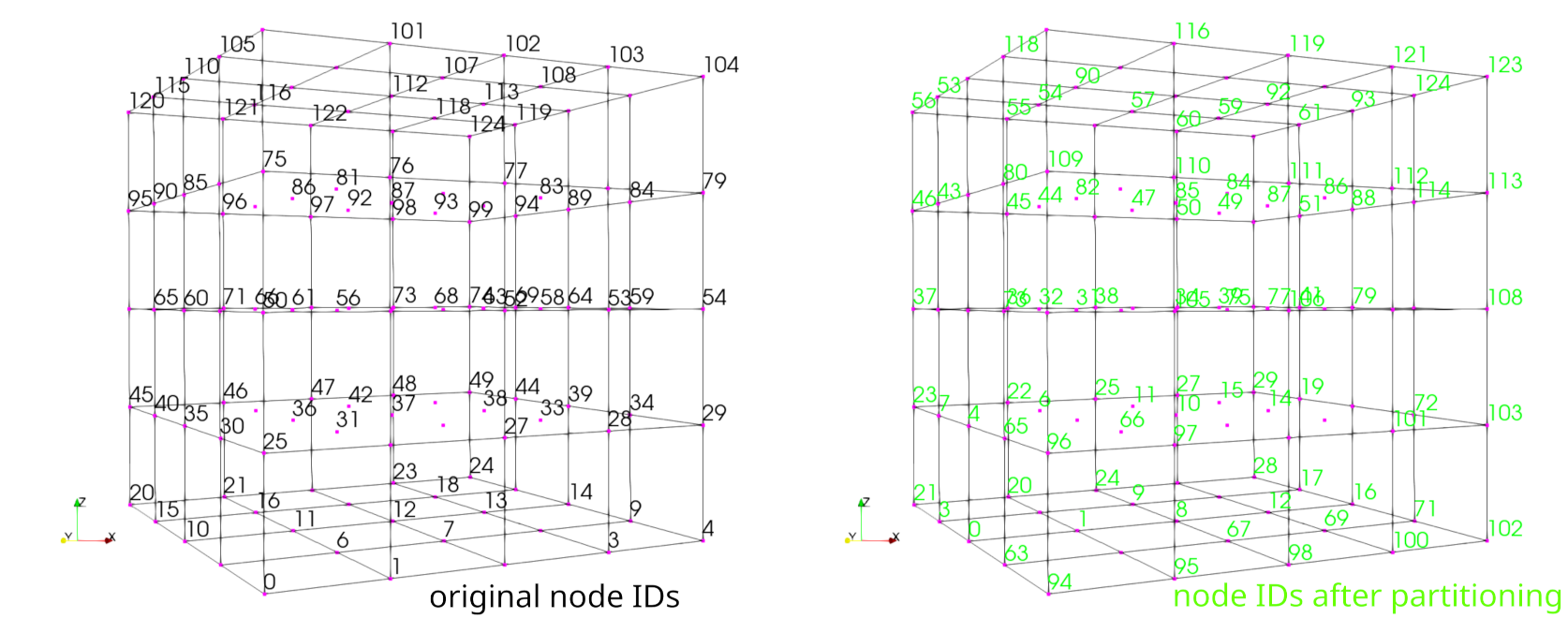
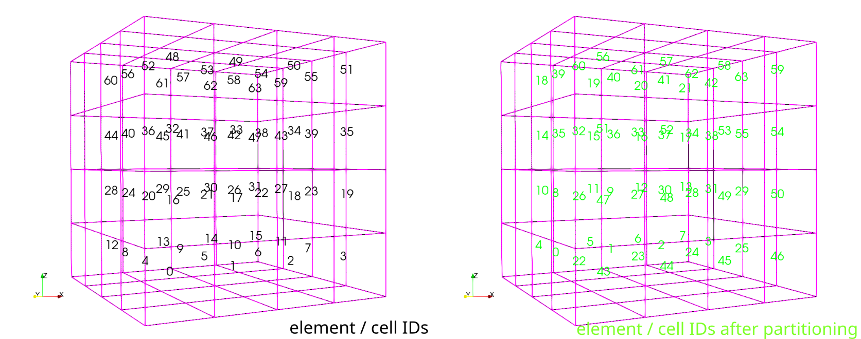
Simple element-wise or node-wise comparisons of simulation results are not possible. The tool ReorderMesh can be applied to reorder the nodes and elements to the initial ordering.

Typically, the workflow is as follows:

graph LR OGS_PARALLEL_SIMULATION_RESULTS(parallel simulation results):::InputStyle -->|pvtu| OGS_REMOVE_GHOST_DATA[pvtu2vtu]:::OGSStyle OGS_REMOVE_GHOST_DATA[pvtu2vtu]:::OGSStyle -->|vtu|OGS_IDENTIFY_SUBDOMAIN(identifySubdomains):::OGSStyle OGS_IDENTIFY_SUBDOMAIN:::OGSStyle -->|vtu with bulk ids|OGS_REORDER_MESH(ReorderMesh):::OGSStyle OGS_REORDER_MESH(ReorderMesh):::OGSStyle -->OGS_REORDERED_PARALLEL_SIMULATION_RESULTS(reordered simulation results):::OGSOutputStyle classDef InputStyle fill:#9090ff classDef OGSStyle fill:#104eb2, color:#ffffff classDef DDCStyle fill:#f2a817 classDef OGSOutputStyle fill:#a0a0f0

A similar workflow is implemented using snakemake for testing the ReorderMesh tool.


This article was written by Thomas Fischer. If you are missing something or you find an error please let us know.
Generated with Hugo 0.122.0 in CI job 430699 | Last revision: February 20, 2024
Commit: [App|PVTU2VTU] Faster computation of unique nodes and mapping d5e28bc  | Edit this page on